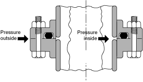
Static Axial Gland Design Application

Gland Design for Static Application for O-rings with Axial Squeeze
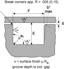
Surface Finish X groove top and bottom : for liquids X = 32 micro inches (0.8 μm Ra)
| • Gland Dimensions Static Application-Face Seal Glands-Metric | ||||||
|---|---|---|---|---|---|---|
| W O-ring Cross Section |
E Gland Depth |
F Groove Width |
R Groove Radius |
|||
| Diam. mm |
Tol. +/- DIN 3771 |
Tol -0/+ | Liquids Tol-0/+.13 |
Vaccum/Gasses | ||
| 0,90 | 0,08 | 0,68 | 0,02 | 1,30 | 1,10 | 0,2 |
| 1,0-1,02 | 0,08 | 0,75 | 0,02 | 1,45 | 1,20 | 0,2 |
| 1,2 | 0,08 | 0,9 | 0,02 | 1,75 | 1,45 | 0,2 |
| 125-1,27 | 0,08 | 0,94 | 0,02 | 1,8 | 1,5 | 0,2 |
| 1,42 | 0,08 | 1,07 | 0,02 | 2,05 | 1,70 | 0,2 |
| 1,5 | 0,08 | 1,13 | 0,02 | 2,2 | 1,80 | 0,2 |
| 1,60 - 1,63 | 0,08 | 1,2 | 0,03 | 2,35 | 1,9 | 0,2 |
| 1,78' - 1,80 | 0,08 | 1,34 | 0,03 | 2,60 | 2,15 | 0,2 |
| 1,90 | 0,08 | 1,43 | 0,03 | 2,75 | 2,30 | 0,2 |
| 2,0 | 0,08 | 1,51 | 0,04 | 2,90 | 2,40 | 0,2 |
| 2,20 - 2,21 | 0,08 | 1,67 | 0,04 | 2,90 | 2,55 | 0,2 |
| 2,40 | 0,08 | 1,82 | 0,04 | 3,20 | 2,80 | 0,2 |
| 2,46 | 0,08 | 1,87 | 0,04 | 3,25 | 2,85 | 0,2 |
| 2,50 | 0,08 | 1,9 | 0,04 | 3,30 | 2,90 | 0,2 |
| 2,62' | 0,08 | 1,99 | 0,04 | 3,50 | 3,05 | 0,2 |
| 2,70 | 0,09 | 2,05 | 0,04 | 3,60 | 3,15 | 0,2 |
| 2,95 | 0,09 | 2,24 | 0,04 | 3,9 | 3,40 | 0,5 |
| 3,0 | 0,09 | 2,27 | 0,04 | 3,9 | 3,45 | 0,5 |
| 3,15 | 0,09 | 2,38 | 0,05 | 4,15 | 3,60 | 0,5 |
| 3,50-3,53 | 0,09 | 2,67 | 0,05 | 4,60 | 4,05 | 0,5 |
| 3,60 | 0,1 | 2,72 | 0,05 | 4,70 | 4,10 | 0,5 |
| 4,0 | 0,1 | 3,03 | 0,06 | 5,25 | 4,60 | 0,5 |
| 4,5 | 0,1 | 3,60 | 0,06 | 6,10 | 5,10 | 0,5 |
| 4,70 | 0,1 | 3,76 | 0,06 | 6,40 | 5,35 | 0,5 |
| 4,8 | 0,1 | 3,84 | 0,06 | 6,50 | 5,45 | 0,5 |
| 5,0 | 0,10 | 4,00 | 0,06 | 6,80 | 5,70 | 0,7 |
| 5,33- 5,34 | 0,13 | 4,26 | 0,08 | 7,25 | 6,05 | 0,7 |
| 5,50 | 0,13 | 4,40 | 0,08 | 7,45 | 6,25 | 0,7 |
| 5,7 | 0,13 | 4,56 | 0,08 | 7,75 | 6,50 | 0,7 |
| 5,80 | 0,13 | 4,64 | 0,08 | 7,90 | 6,60 | 0,7 |
| 6,0 | 0,13 | 4,98 | 0,08 | 7,80 | 7,75 | 0,7 |
| 6,40 | 0,13 | 5,31 | 0,1 | 8,30 | 7,20 | 0,7 |
| 6,50 | 0,13 | 5,40 | 0,1 | 8,40 | 7,3 | 0,7 |
| 6,9 | 0,13 | 5,73 | 0,1 | 8,95 | 7,75 | 0,7 |
| 6,99 | 0,15 | 5,80 | 0,1 | 9,05 | 8,85 | 0,7 |
| 7,0 | 0,15 | 5,81 | 0,1 | 9,05 | 7,90 | 1,0 |
| 7,5 | 0,15 | 6,23 | 0,1 | 9,70 | 8,40 | 1,0 |
| 8,0 | 0,18 | 6,64 | 0,1 | 10,35 | 9.00 | 1,0 |
| 8,40 | 0,18 | 6,97 | 0,15 | 10,90 | 9,45 | 1,0 |
| 9,0 | 0,2 | 7,65 | 0,15 | 11,10 | 10,40 | 1,0 |
| 10,0 | 0,2 | 8,5 | 0,15 | 12,30 | 11,55 | 1,0 |
| 11 | 0,2 | 9,35 | 0,15 | 13,55 | 12,7 | 1,0 |
| 12,0 | 0,2 | 10,2 | 0,15 | 14,80 | 13,85 | 1,5 |
| 13,0 | 0,2 | 11,05 | 0,15 | 16,00 | 15.00 | 1,5 |
| 14,0 | 0,2 | 11,9 | 0,3 | 17,25 | 16,15 | 1,5 |
| 16 | 0,2 | 13,6 | 0,3 | 19,70 | 18,45 | 1,5 |
| 18 | 0,2 | 15,30 | 0,3 | 22,15 | 20,80 | 1,5 |
| 20 | 0,2 | 17,00 | 0,3 | 24,65 | 23,10 | 1,5 |
for vacuum and gases X = 16 micro inches (0.4 μm Ra)
groove sides: X = 63 micro inches (1.6 μm Ra)