Engineering Design Guide for Gland Clearance

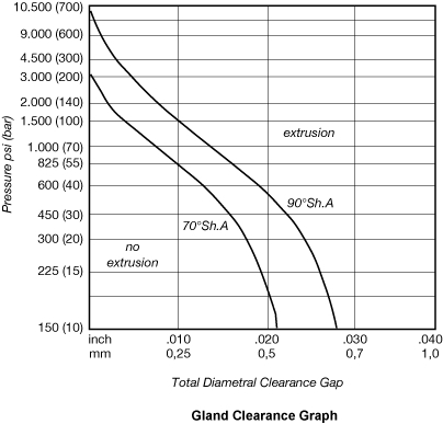
The gland clearance diagram gives a guide to the relation between hardness, pressure, clearance, and extrusion. This figure is based on NBR O-rings with a cross section of .139 inch (3,53 mm) without back up rings. When there is risk for extrusion use contoured hard rubber or plastic back-up rings. The results are based on tests at temperatures up to 70°C.
Note: for silicone and fluorosilicone O-rings reduce all the clearances shown by 50%.
The most effective and reliable sealing is generally provided with the diametrical clearance as shown in Table 3.B1a. The maximum allowable gaps are indicated for 70°hardness O-rings with different cross sections without back-ups for reciprocating and static seals. These values correspond to a pressure of ca. 1200 PSI (80 bar) (8 Mpa) at 70°F (21°C). When greater clearances occur, the diagram indicates conditions where O-ring seals may be used - depending on the fluid pressure and O-ring hardness. [See Table]
| Gland clearance in relation to hardness and 0-ring cross section | |||
|---|---|---|---|
| Cross section | Max. clearance 70 ° Shore A | ||
| Inch | mm | inch | mm |
| .070 | 1,0-2,0 | .002 - .004 | 0,05 - 0,1 |
| .103 | 2,0-3,0 | .002 - .005 | 0,05 - 0,13 |
| .139 | 3,0-4,0 | .002 - .006 | 0,05 - 0,15 |
| .210 | 4,0-6,0 | .003 - .007 | 0,07 - 0,18 |
| >.275 | >6,0 | .004 - .010 | 0,1 - 0,25 |
| Gland Clearance Table | |||