

Static Radial Glans Design Application
Gland Design for Static Application for O-rings with Radial Squeeze Industrial Radial Glands INCHES
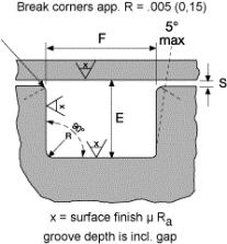
Surface Finish X groove top and bottom : for liquids X = 32 micro inches (0.8 μm Ra)
groove sides: X = 63 micro inches (1.6 μm Ra)
| Gland Dimensions Static Seals - Industrial Radial Applications (Indies) | ||||||||||
|---|---|---|---|---|---|---|---|---|---|---|
| 0-ring Cross section W |
Gland Depth. Radial Static E |
Static Squeeze for Radial Seals | Clearance Diametral | Groove Width F |
Groove Radius R |
Max. Allowable Eccenaicity | ||||
| Nominal | Actual | Actual | % | Standard | One Backup Washer; | Two Backup Washers: | ||||
| 1/16 | 0.07 | .050/.052 | .015/.023 | 22/32 | '.002 min. | .093/.098 | .138/.143 | .205/.210 | .005/.015 | .005/.015 |
| 3/32 | 0.103 | .081/.083 | .017/.025 | 17/24 | *.002 min. | .14W.145 | .171/.176 | .238/.243 | .005/.015 | .006/.015 |
| 1/8 | 0.139 | .111/.113 | .022/.032 | 16/23 | '.003 min. | .187/.192 | .208/.213 | .275/.280 | .010/.025 | .010/.025 |
| 3/16 | 0.21 | .170/.173 | .032/.045 | 15/21 | '.003 min. | 281/.288 | 311/.316 | .410/.415 | 020/.035 | 020/.035 |
| 1/4 | 0.275 | .226/.229 | .040/.055 | 15/20 | '.004 Mn. | .375/.380 | .408/.413 | .538/.543 | .020/.035 | .020/.035 |
| 1. Total indicator Reading between groove and adjacent bearing surface. | ||||||||||
| 2. These groove dimensions are for compounds that free swell less than 15%. Sutibable allowances should be mde for higher swell compounds | ||||||||||
| •For max. allowable clearance, refer to fig 22 to determine value based upon pressure requirement and compound hardness. | ||||||||||
| •Maximum clearance should be reduced by 1/2 for compounds exhibiting poor strength such as silicone and fluorosilicone. | ||||||||||
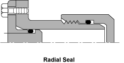
| Male plug dimentsions and female throat (bore) dimensions must be calculated based upon maximum and minimum clearance gaps | ||||||||||
