

Dovetail O-ring Groove Design Guide - Inches
Dovetail Gland Design for Static Applications
There are numerous static groove styles for O-rings, each with unique distinctions for individual uses. Dovetail grooves are special glands designed to hold O-rings in place during equipment assembly and maintenance. The timings for machining and O-ring installation are factors to consider when determining groove style. The best gland design for your application will vary based on project, intention, and personal preference.
Dovetail Seals Explained
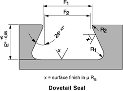
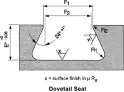
This diagram displays intricate and precise measurements for dovetail grooves, where X equals the surface finish in μ Ra. Measurements include:
- Groove Top & Bottom for Liquids: X = 32μ (0.8 μm Ra)
- Vacuum & Gases: X = 16μ (0.4 μm Ra)
- Groove Sides: X = 63μ (1.6 μm Ra)
Contact Ace Seal to learn more.
Groove Dimensions for Dovetail O-Ring Grooves
Inches
The dimensions for your dovetail groove must be highly accurate with high tolerances for precision. The depth, width, and radius refer to the dimensions of the dovetail groove in inches, while the squeeze percentage describes the physical amount of squeeze that the O-ring experiences in the groove.
Use our inches gland dimension chart to determine the appropriate gland depth, squeeze, width, and radius for your AS568 O-rings.
| Gland Dimensions Dovetail Grooves, Inches | ||||||
|---|---|---|---|---|---|---|
| 0-ring Cross Section w |
Gland Depth E |
Squeeze % | Groove Width to Sharp Corner F2 |
Groove Radius | ||
| 1/16 | .070 | .050/.052 | 27 | .055/.059 | .005 | .015 |
| 3/32 | .103 | .081/.083 | 21 | .083/.087 | .010 | .015 |
| 1/8 | .139 | .111/.113 | 20 | .113/.117 | ..010 | .030 |
| 3/16 | .210 | .171/173 | 18 | .171/.175 | .015 | .030 |
| 1/4 | .275 | .231/.234 | 16 | .231/.235 | .015 | .060 |
| 3/8 | .375 | .315/.319 | 16 | .315/.319 | .020 | .090 |
Learn about gland dimensions in metric sizes from our metric dovetail groove guide, or view the Parker Handbook for more information.
Using Dovetail Seals for O-Ring Applications
Dovetail grooves are specialty glands for mounting O-rings to resist dislodging during maintenance. They are specifically designed to create a secure placement of an O-ring within a face-type groove to prevent it from falling out. While particularly useful for vacuum applications, these glands are complex and expensive to machine and, as such, are not generally recommended to be used unless absolutely required. Additionally, the dovetail groove construction is only recommended for O-rings with cross sections of .139” (3.53mm) or larger. Dovetail glands require explicit conditions and precise projects.
Dovetail grooves are used for applications across a wide variety of industries. Specific projects and uses will vary based on individual requirements and specifications.
O-Rings for Dovetail Grooves
Dovetail grooves are compatible with numerous styles of rubber O-rings. Ace Seal offers standard and custom AS568 O-rings with customizable inside diameters, cross sections, materials, hardness, and colors. Custom components are designed to suit your needs and specific applications. At Ace Seal, we have the correct O-rings for all your sealing needs.
Contact Ace Seal
Ace Seal is your trusted provider of superior sealing products and accessories. Contact us for more information about dovetail-compatible O-rings, or request a quote to place your order today.
